Preparing a target board for debugging
When you want to debug a program on a target board, usually some modifications of the hardware are necessary. The general rule is that the lines used for debugging should not have any resistive or capacitive loads or active components on them.
Preparing a debugWIRE target
Since the RESET line is used for communication between the MCU and the debug probe, no capacitors should be connected to it. Similarly, pull-up resistors should not be stronger than 10 kΩ. And, there should be no active reset circuit connected to this line. In other words, before debugging starts, disconnect such components from the RESET line.
Arduino Uno and clones
On the Arduino Uno and similar boards, an auto-reset capacitor is usually connected to the RESET line, as shown below.
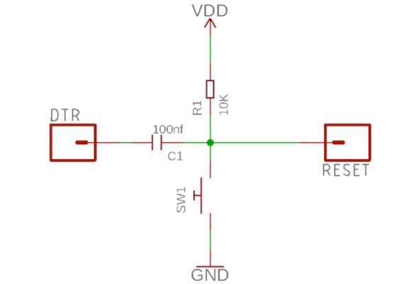
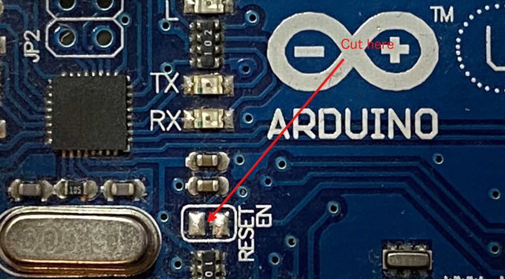
This is responsible for issuing a reset signal when a serial connection is established to the board, which starts the bootloader, which then expects a HEX file sent by the Arduino IDE. On the original Uno board, there is a solder bridge marked 'RESET EN' that needs to be cut to disconnect the capacitor.
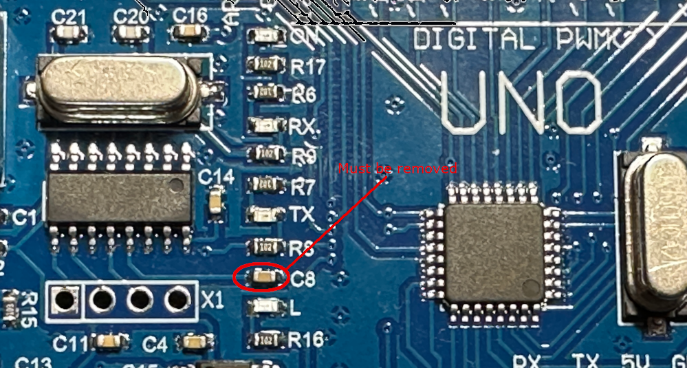
On clone boards with a CH340 serial converter chip, you may have to remove the capacitor marked C8.
Arduino Nano and clones
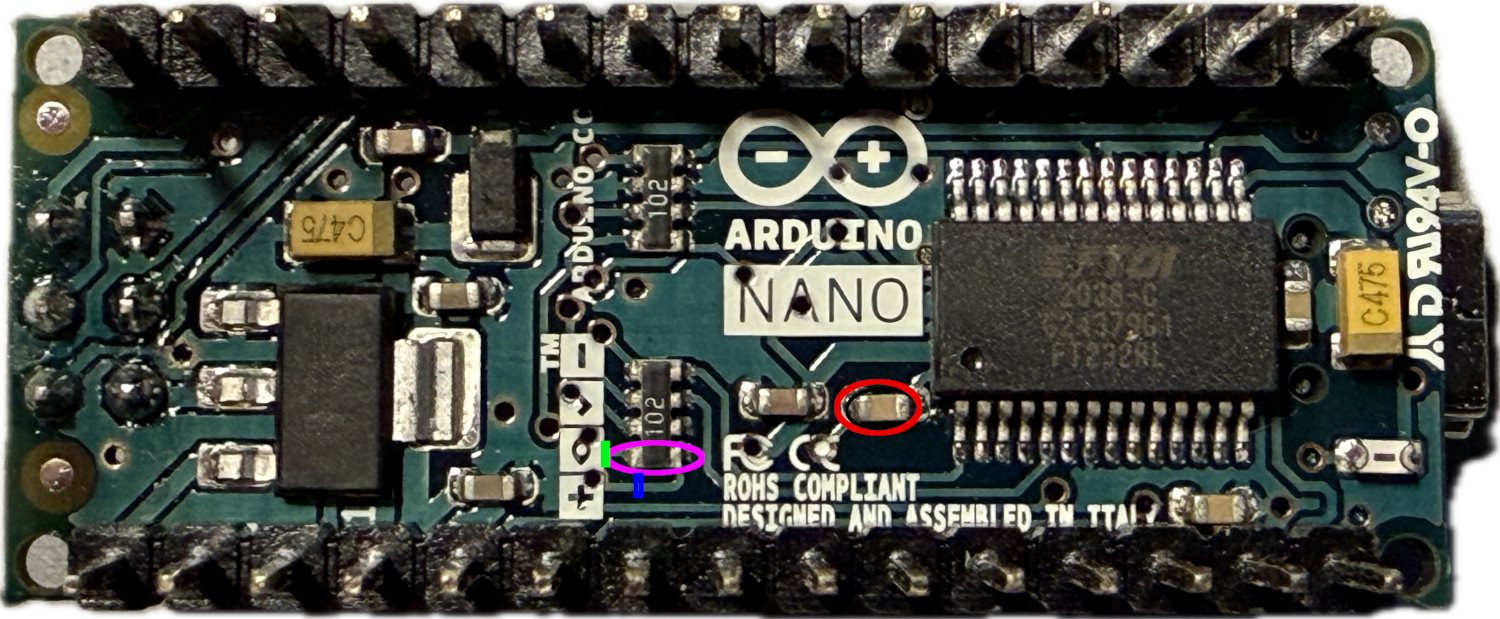
Things are a bit more complicated with Arduino Nano boards. Here, you not only have to remove the auto-reset capacitor but also a strong pull-up resistor of 1kΩ on the RESET line. The following picture shows the bottom side of an Arduino Nano V3.3. The capacitor to be removed has been marked by a red ellipse, the 1kΩ resistor by a magenta one. Since this resistor is part of a resistor array, one needs to cut the trace instead. If you manage to cut the trace at the point marked by the green line, everything is fine. If you are not able to accomplish that, cutting at the point marked by the blue line is also OK. In this case, the power LED will also be cut off. In any case, after this modification, this board will probably only be usable for debugging purposes.
For Arduino Nano clones (those using a CH340 as the serial converter), one can remove the resistor and the capacitor marked in the following picture, as described by denMike.
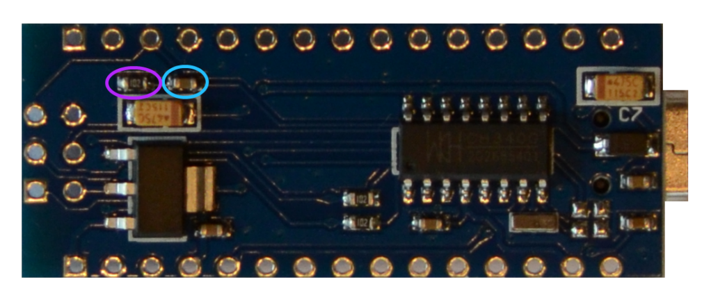
Note, however, that there are many different versions of Nanos on the market. Verify that making the changes will indeed accomplish what you are after: Removing the capacitive and resistive load from the RESET line.
Arduino Pro Mini and clones
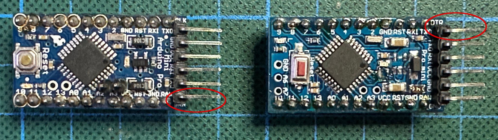
The Arduino Pro Mini is a simpler case. The pull-up resistor has a resistance of 10 kΩ, and the auto-reset capacitor is not connected as long as nothing is connected to the DTR pin. This is the header pin, either labeled DTR or GRN. On the original Sparkfun board (left), this is the bottom pin; on some clones (right), it is the top one.
Other ATmegaX8 boards
For other boards with ATmega168 and ATmega328 chips, the situation is similar. Find out what is connected to the RESET line and disconnect any capacitors and strong resistors. And the same holds for other debugWIRE MCUs.
Preparing a JTAG target
JTAG targets are easier to deal with. Simply do not connect anything to the JTAG lines (TDI, TDO, TMS, TCK). On an Arduino Mega or Mega 2560, these are the analog pins A4-A7. On a Leonardo, these are the analog pins A0-A3. While physical changes on the board are not necessary, it is very likely that the JTAG pins have to be enabled by setting the corresponding fuses. It also means that one should disconnect anything from those lines.
Preparing a UPDI target
Again, UPDI targets are easy to deal with. Ensure that there is no capacitive or resistive load or active component on the UPDI line and that the UPDI pin is accessible.
On the Nano Every, for example, this pin cannot be accessed through the board pins, but there is a pad on the backside of the PCB that can be used to access the UPDI line. And the USB-UART converter is usually disconnected from this pin. On the Uno WIFI Rev2, again, the UPDI pin is not exposed. But on this board, a mEDBG debugger is implemented. So you can connect to this debugger.
Problems arise when the UPDI pin is used as a GPIO or a RESET line. For this, consult the section on fuse preparations for UPDI targets.